Dwayne Herzberg.
Solar Tracker
This Solar Tracker is an embedded system that uses an Arduino or ESP32 microcontroller to track the sun's position and adjust the angle of a solar panel accordingly. By tracking the sun’s movement throughout the day, the Solar Tracker ensures the solar panel is always optimally positioned for maximum energy production.
Solar tracker with ARDUINO or ESP32 and soltrack-2.2 library
Warning: This project is still in development.
CAD files: The SolidWorks files are available in the provided zip file. You can use them to simulate the panel's movement and 3D print the required parts. The software is designed to be adaptable to any solar panel, so feel free to modify it to suit your specific needs.
The system computes the sun’s position using the SolTrack 2.2 library. This project supports two microcontrollers: Arduino and ESP32.
Features
| Feature | Arduino | ESP32 |
|---|---|---|
| Microcontroller | Arduino UNO/MEGA2560 | ESP32 |
| Time Management (RTC) | Manual adjustment of date and time | Automatic adjustment via Wi-Fi |
| Wi-Fi Connectivity | Not available | Available |
| MQTT Support | Not available | Fully supported for Home Assistant |
| Motor Control (Azimuth/Elevation) | Supported | Supported |
| Joystick Control | Supported | Supported |
| Anemometer | Supported | Supported |
| Solar Position Calculation | Supported | Supported |
how it works
Azimuth Control Overview
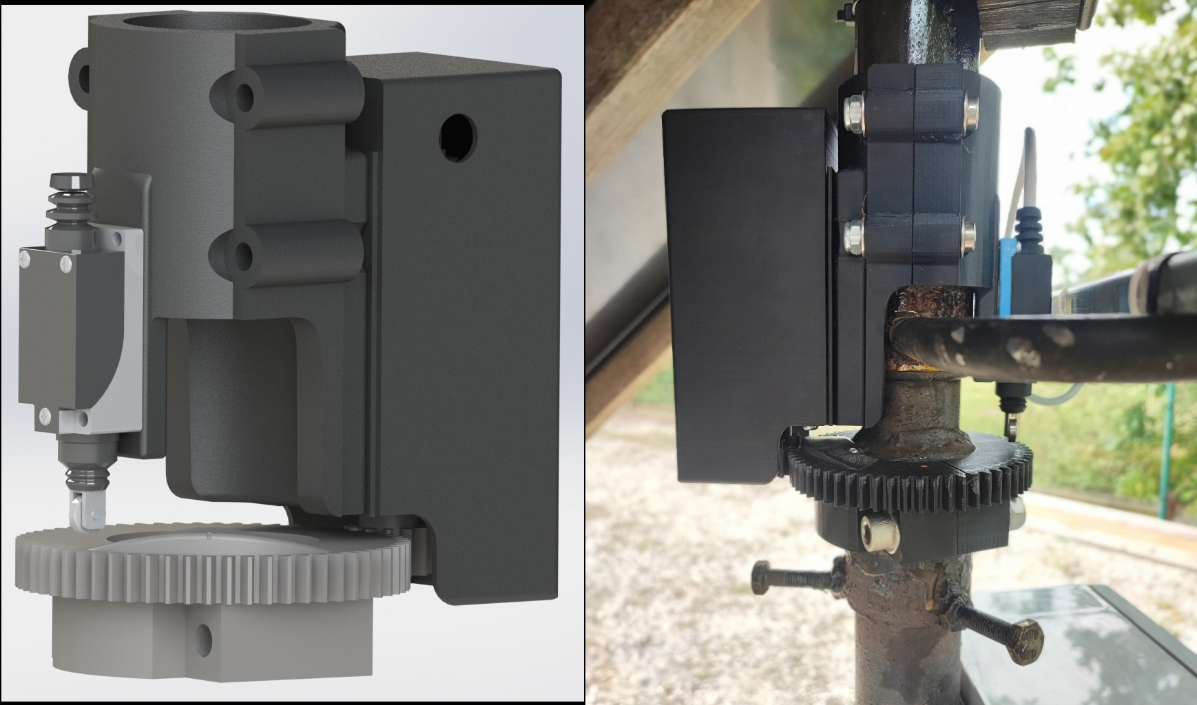
The azimuth controller manages the solar panel's horizontal movement, powered by a motor controlled via a BTS7960 driver. A southward limit switch acts as a reference to stop the motor when the panel reaches the defined position, preventing excessive rotation.
Pin Configurations
| Component | Arduino | ESP32 |
|---|---|---|
| Motor Enable Pin | Pin 4 | GPIO 19 |
| PWM Left (Move Left) | Pin 6 | GPIO 18 |
| PWM Right (Move Right) | Pin 5 | GPIO 17 |
| Limit Switch | Pin 7 | GPIO 16 |
Calibration and Movement
At startup, the solar tracker goes through a calibration process to measure how long it takes for the panel to rotate fully from one side to the other (from 0° to 360° azimuth). Once calibrated, the tracker is able to adjust the azimuth angle by calculating the time needed to reach the desired position. The system also checks if the target azimuth angle is within the allowed range (AZIMUTH_DEG_MIN to AZIMUTH_DEG_MAX). If outside, the movement is canceled.
Limit Switch
The limit switch ensures the panel doesn’t exceed its bounds, defining 0° (or 360°) when pressed. If triggered during operation, the motor stops immediately. It also acts as a reference point to determine the panel's azimuth angle.
Here is a summary of the azimuth control parameters, as defined in config.h:
| Parameter | Value |
|---|---|
| AZIMUTH_MOTOR_PIN_EN | Motor enable pin |
| AZIMUTH_MOTOR_PWM_PIN_L | Motor PWM pin for left |
| AZIMUTH_MOTOR_PWM_PIN_R | Motor PWM pin for right |
| AZIMUTH_LIMIT_SWITCH_PIN | Limit switch pin |
| AZIMUTH_DEG_MAX | 275.0° (maximum azimuth allowed) |
| AZIMUTH_DEG_MIN | 90.0° (minimum azimuth allowed) |
| AZIMUTH_TIME_THRESHOLD | Minimum time threshold (optional) |
Elevation Control Overview
The elevation controller manages the solar panel’s vertical tilt, tracking the sun's altitude. This is done via an actuator controlled by a BTS7960 motor driver.
Note: Relay or H-Bridge could work, I used a BTS7960 cause i had one laying around.
Pin Configurations for Arduino and ESP32
| Component | Arduino | ESP32 |
|---|---|---|
| Motor Enable Pin | Pin 8 | GPIO 26 |
| PWM Up (Extend) | Pin 10 | GPIO 27 |
| PWM Down (Retract) | Pin 9 | GPIO 14 |
Calibration and Movement
To ensure correct actuator operation, use the datasheet to configure ELEVATION_ACTUATOR_SPEED and ELEVATION_ACTUATOR_LENGTH. These parameters calculate the time required to fully extend or retract the actuator. If real-world conditions vary, override this time using the FORCE_TIME_FULL_TRAVEL parameter.
Warning: Keep the PWM speed at 255 (maximum) for accurate time calculations during extension and retraction.
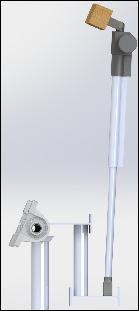
At initialization, the system calibrates the actuator, setting the panel to a 90° (horizontal) position for safety. The elevation range is constrained by the actuator’s length and physical limits of the panel. Customize ELEVATION_DEG_MIN and ELEVATION_DEG_MAX based on your setup.
I used SolidWorks to simulate the panel’s movement and constraints.
Key Parameters in config.h
| Parameter | Value |
|---|---|
| ELEVATION_MOTOR_PIN_EN | Motor enable pin |
| ELEVATION_MOTOR_PWM_PIN_U | PWM pin for extension (up) |
| ELEVATION_MOTOR_PWM_PIN_D | PWM pin for retraction (down) |
| ELEVATION_DEG_MAX | 90.0° |
| ELEVATION_DEG_MIN | 19.0° |
| ELEVATION_MOTOR_PWM_SPEED | 255 (maximum motor speed) |
| ELEVATION_ACTUATOR_SPEED | 5 mm/s |
| ELEVATION_ACTUATOR_LENGTH | 350 mm |
| FORCE_TIME_FULL_TRAVEL | Forced full travel time (in seconds) |
Anemometer Control Overview
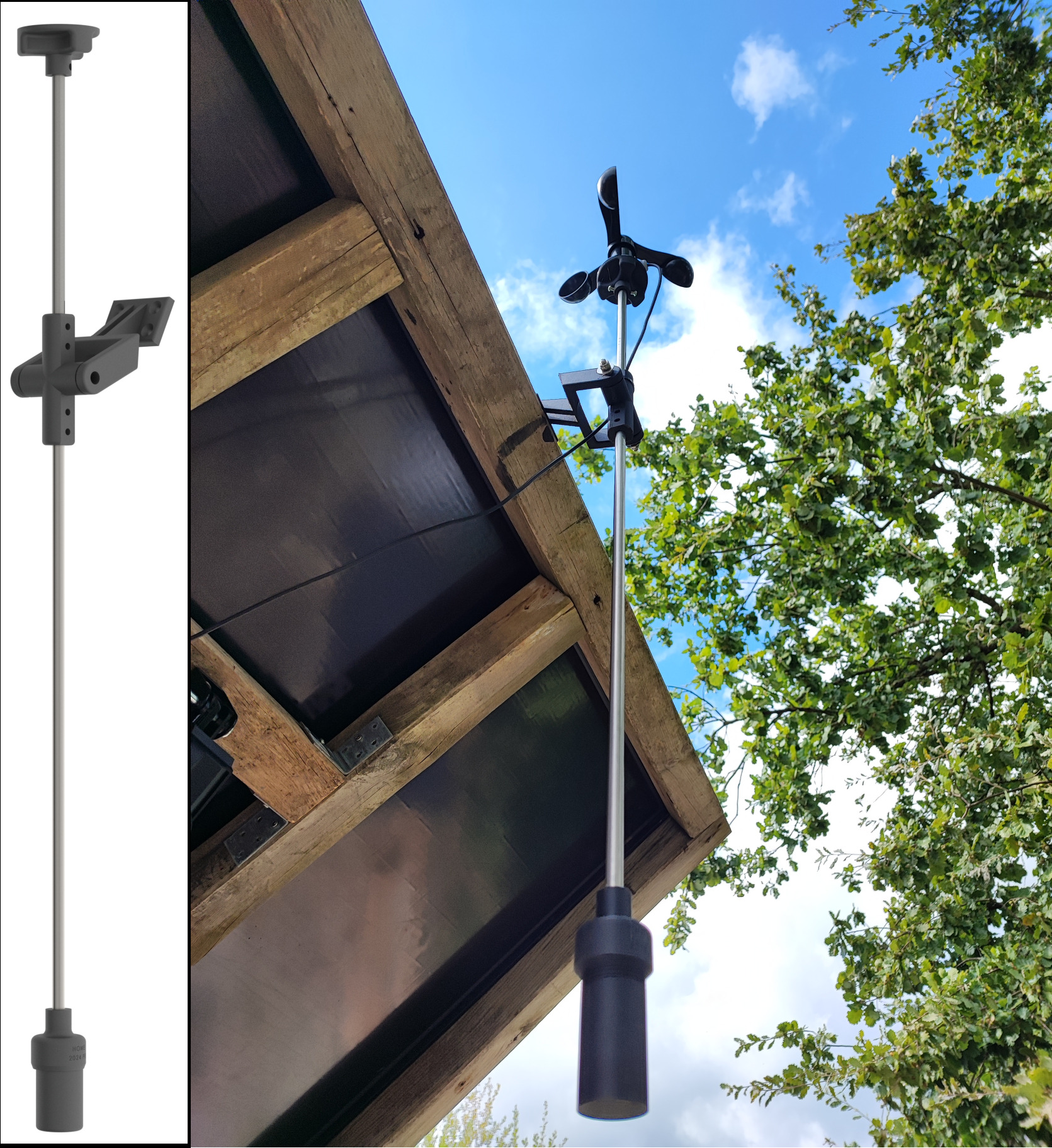
The anemometer is a 3-wire sensor that operates independently from the solar tracker. It monitors wind speeds and ensures the safety of the solar panel during high wind conditions. When the wind speed exceeds 5 m/s, the anemometer activates a relay, sending an alarm signal to the solar tracker.
The solar tracker continuously monitors the alarm signal through a dedicated GPIO pin. If the wind speed exceeds 5 m/s, the tracker moves the solar panel to a safety position for 15 minutes. If the wind speed remains high and the alarm is triggered again during this countdown, the 15-minute timer resets. The panel remains in the safety position until wind conditions stabilize.
Pin Configuration for Anemometer
| Component | Arduino | ESP32 |
|---|---|---|
| Wind Alarm Detection Pin | Pin 11 | GPIO 13 |
Key Parameters in config.h
| Parameter | Value |
|---|---|
| ANEMOMETER_BUTTON_PIN | Pin for alarm detection |
| ANEMOMETER_SAFE_DURATION | 15 minutes (900,000 ms) |
Here’s an updated version of the Joystick Control Overview:
Joystick Control Overview
The joystick allows manual control of the solar panel's movement. By moving the joystick, the user can command the system to adjust the panel’s azimuth (horizontal) and elevation (vertical) angles, according to the inputs detected on the VRX and VRY pins. Additionally, user have to press the joystick button for 5 seconds to enable the joystick control. Same action to disable it.
Pin Configuration for Joystick
| Component | Arduino | ESP32 |
|---|---|---|
| VRX Pin (Horizontal) | A0 | GPIO 32 |
| VRY Pin (Vertical) | A1 | GPIO 33 |
| Button Pin (Switch) | Pin 2 | GPIO 25 |
MQTT Support Overview
The MQTT protocol is used to communicate with the Home Assistant platform. The solar tracker publishes data to the MQTT broker, which is then read by Home Assistant to display the solar panel’s information. The system has been made with automatic discovery, allowing Home Assistant to recognize the solar tracker and its entities.

Hardware Used
This is a non-exhaustive list of the components used in this project:
| Component | Link |
|---|---|
| ESP32 Devkit | https://www.amazon.fr/dp/B0CLD28SHQ |
| ESP32 Expansion Board | Delivered with the ESP32 Devkit |
| 2x BTS7960 Motor Drivers | https://www.amazon.fr/dp/B09MHNG2JS |
| RTC DS3231 | https://www.amazon.fr/dp/B077XN4LL4 |
| Joystick | N/A |
| Anemometer | N/A |
| DC Motor 12V | N/A |
| Linear Actuator | https://www.amazon.fr/dp/B0CWN28GFL |
| Limit Switch TZ-8122 | N/A |
The Solar Tracker Structure
wooden frame
The wooden frame is a custom-made structure that is designed to hold and position two solar panels. It is constructed using 6 separate pieces of wood that are joined together to form a sturdy base. The Wood Support is an essential component of the Solar Tracker system, as it provides a stable platform for the panels to rest on. The Wood Support is designed to accommodate solar panels with a total size of 1605mm x 2176mm, and provides a total area of 1.73 square meters of surface area for capturing the sun's energy.
The frame is composed of 6 pieces with the following dimensions:
- 68x68x2245 mm
- 68x68x2109 mm
- 68x68x1544 mm
![]()
The mast
The mast is divided into two parts to facilitate the azimuth rotation of the wooden frame. The elevation rotation is achieved through the use of two complete ball bearings (SKF UCP 207).
The mast stands at a height of 1.70m.
![]()
Special thanks to the SolTrack library
Thanks to the soltrack-2.2 library. This library is used to calculate the sun's position based on the date, time, and location. The library provides the azimuth and elevation angles of the sun, which are used to adjust the solar panel's position.


